Product Description
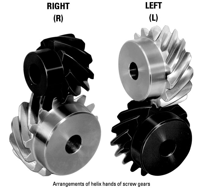
Jacton Industry offers Heavy Duty Transmission Worm Gear Screw Jack Electric Screw Jacks,2.5ton Electric Screw Lift Motor Proximity Switches and 3-Phase Motor meet your requirements. Prevents the screw from being removed from the jack gearbox. Fitted as standard on ball screw. Optionally available for worm gear screw jacks with trapezoidal screws. The stop collar cannot be used as a fixed stop. In addition to the extensive standard range, we can also supply anticlockwise, multi-start and special material worm gear screw jacks on request.
2.5 tonnes worm electric screw lift jacks (cubic design) are high quality engineering products for precise lifting, lowering and pivoting of loads, and are, under normal operation, maintenance free. This motor jack is in a trunnion mounting arrangement, the screw has a CZPT on the end and the jack body is mounted on a large pivoting frame, or trunnion. This type of mounting is particularly common in the antenna industry. In practice, the CZPT should be as close to the centerline of the internal nut as design permits. Its features cover CZPT lead screw Tr 30×6, stroke 66567X3, registered Capital 500000CNY) is a leading manufacturer and supplier of Screw Jacks (Mechanical Actuators), Bevel Gearboxes, Lifting Systems, Electric Linear Actuators, Gearmotors and Speed Reducers, Others Linear Motion and Power Transmission Products in China. Most of them are passed CE certificates. We are located in Chang An, Xihu (West Lake) Dis. guan, Guang dong in China. We are an audited professional manufacturer and supplier by SGS (Serial NO.: QIP-ASI192186) and BV (Serial NO.: MIC-ASR257162) organizations. We have a strict quality system, with senior engineers, experienced skilled workers and practiced sales teams, and consistently provide the customers with the best engineered solution for precision linear actuation, power transmission and mechanical jacking systems. CZPT Industry guarantees quality, reliability, performance and value for today’s demanding industrial applications.
Company Advantages
* One of the biggest orders with 1750 units screw lift jacks.
* Standard products with 2D Drawings(DXF, DWG, PDF) and 3D CAD Model(STEP).
* 100% quality assured with double quality inspections. Original Inspection Reports, Operation Manual, and Book Catalogue are put into the packages.
* 100% safety transportation with strong standard export plywood cases materials (free fumigation).
* International standard materials for all standard products.
* Custom design available, OEM service available, Free engineering advice and Customer label available.
Products List
* Manual Screw Jacks
* Electric Screw Jacks
* Screw Jacks Series:
Cubic Screw Jack JTC Series, Machine Screw Jack JTW Series, Trapezoidal Screw Jack JT Series, Worm Screw Jack JTM Series, Stainless Steel Screw Jack JSS Series, Through Hole Screw Jack JTH Series, Ball Screw Jack JTB Series, Cubic Ball Screw Jack JTD Series, Bevel Gear Screw Jack JTS Series, and Electric Cylinder JTE Series.
* Bevel Gearboxes Series:
Cubic Bevel Gearbox JTP Series, Hollow Shaft Gearbox JTPH Series, Input Flange Gearbox JTPF Series, Input Flange and Hollow shaft Gearbox JTPG Series, Stainless Steel Gearbox JTP Series, Aluminum Gearbox JTA Series, and Spiral Bevel Gearboxes JT Series.
* Screw Jack Lifting Systems and Accessories:
2jacks lifting system, 3jacks lifting system, 4jacks lifting system, 6jacks lifting system, 8jacks lifting system……14jacks lifting system. Lifting systems accessories cover ac, dc motors, geared motors, servo motors, stepper motors, handwheels, couplings, universal joints, telescopic universal joints, connecting shafts, cardan shafts, limit switches, proximity switches, safety nut, travel nut, rod ends, stop nuts, pillow block bearings, flange blocks, motor flange nema or iec, encoder, potentiometer, frequency converter, position indicators, trunnion plate, and trunnion mounting brackets.
* Electric Linear Actuators Series:
Electro Mechanical Actuators LA Series, Electro Mechanical Actuators LAP Series.
* Gear Reducers Series:
Helical Gear Reducers R Series, Helical Bevel Gear Reducers K Series, Parallel Shaft Helical Gear Reducers F Series, Helical Worm Gear Reducers S Series, Helical Gear Motor GMH/GMV Series, and Worm Gear Reducers NMRV Series.
Customers Distribution Countries
* American Countries: United States, Mexico, Canada, Chile, Argentina, Xihu (West Lake) Dis.via, Brazil, Colombia, Guatemala, Honduras, Panama, Peru.
* European Countries: Germany, France, United Kingdom, Italy, Spain, Poland, Romania, Netherlands, Belgium, Greece, Czech Republic, Portugal, Sweden, Hungary, Austria, Switzerland, Bulgaria, Denmark, Finland, Slovakia, Norway, Ireland, Georgia, Slovenia.
* Asian Countries: Malaysia, Indonesia, Singapore, Philippines, Vietnam, Thailand, India, Israel, Cambodia, Myanmar, Sri Lanka, Maldives, Pakistan, Iran, Turkey, Jordan, Saudi Arabia, Yemen, Oman, United Arab Emirates, Qatar, Georgia, Armenia.
* Oceanian Countries: Australia, New Zealand.
* African Countries: Egypt, Ethiopia, Nigeria, South Africa, Zambia, Mozambique.
| Application: | Motor, Electric Cars, Motorcycle, Machinery, Marine, Agricultural Machinery, Car, Lifting System, Lift Table, Lifting Platform |
|---|---|
| Installation: | Vertical Type |
| Layout: | Right Angle Drive |
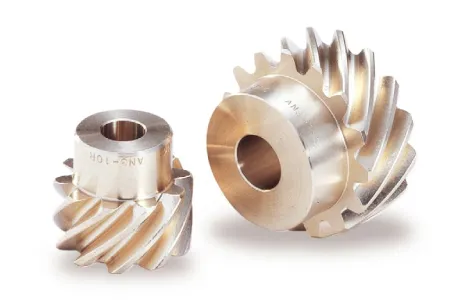
| Gear Shape: | Worm Gear |
| Step: | Single-Step |
| Type: | Worm Reducer |
| Customization: |
Available
| Customized Request |
|---|
How do you install a screw gear system?
Installing a screw gear system, also known as a worm gear system, requires careful consideration and precise execution. Here’s a detailed explanation of the steps involved in installing a screw gear system:
- Design and Selection: Before installation, it is crucial to design and select the appropriate screw gear system for the specific application. Consider factors such as required torque, speed, load capacity, gear ratio, and environmental conditions. Choose a screw gear system that matches the application’s requirements and ensure compatibility with other components and machinery.
- Prepare the Components: Gather all the necessary components for the screw gear system installation, including the worm gear, worm wheel, bearings, shafts, and any additional accessories or support structures. Inspect the components for any damage or defects and ensure they are clean and properly lubricated.
- Mounting the Worm Gear: Begin the installation by mounting the worm gear. Securely attach the worm gear to the appropriate shaft or motor using suitable fasteners. Ensure that the alignment of the worm gear is accurate, and it is properly centered on the shaft to avoid any misalignment issues during operation.
- Mounting the Worm Wheel: Once the worm gear is in place, mount the worm wheel. The worm wheel should be positioned in such a way that it meshes smoothly with the worm gear. Ensure that the worm wheel is securely mounted, and any necessary bearings or supports are properly installed to maintain stability and alignment.
- Alignment and Adjustment: Proper alignment of the screw gear system is crucial for its efficient operation. Ensure that the worm gear and worm wheel are correctly aligned both axially and radially. Check for any excessive play or binding in the system. Make necessary adjustments to achieve optimal alignment and smooth meshing between the gears.
- Lubrication: Apply the recommended lubricant to the screw gear system. Proper lubrication is essential to minimize friction and wear, ensuring smooth operation and extending the system’s lifespan. Follow the manufacturer’s guidelines regarding the type and amount of lubricant to use.
- Testing and Fine-Tuning: After installation, perform thorough testing of the screw gear system. Check for smooth operation, proper engagement between the gears, and any abnormal noise or vibration. Fine-tune the system if necessary, making adjustments to achieve the desired performance and ensure optimal functionality.
- Regular Inspection and Maintenance: Once the screw gear system is installed and operational, it is important to establish a regular inspection and maintenance schedule. Regularly inspect the system for signs of wear, lubrication levels, and any potential issues. Perform routine maintenance tasks such as cleaning, lubrication replenishment, and component replacement as needed.
It is crucial to follow the manufacturer’s guidelines and specifications during the installation process. If unsure about any aspect of the installation, consult with experts or refer to the manufacturer’s documentation for detailed instructions specific to the screw gear system being installed.
How do you address thermal expansion and contraction in a screw gear system?
Addressing thermal expansion and contraction in a screw gear system is crucial to ensure the proper functioning and longevity of the system. Thermal expansion and contraction occur when a system is subjected to temperature changes, leading to dimensional changes in the components. Here’s a detailed explanation of how to address thermal expansion and contraction in a screw gear system:
- Material Selection: Choose materials for the screw gear system components that have compatible coefficients of thermal expansion (CTE). Using materials with similar CTE can help minimize the differential expansion and contraction between the components, reducing the potential for misalignment or excessive stress. Consider materials such as steel, bronze, or other alloys that exhibit good dimensional stability over the expected operating temperature range.
- Design for Clearance: Incorporate proper clearances and tolerances in the design of the screw gear system to accommodate thermal expansion and contraction. Allow for sufficient clearance between mating components to accommodate the expected dimensional changes due to temperature variations. This can prevent binding, excessive friction, or damage to the gears during temperature fluctuations.
- Lubrication: Utilize appropriate lubrication in the screw gear system to mitigate the effects of thermal expansion and contraction. Lubricants can help reduce friction, dissipate heat, and provide a protective film between the mating surfaces. Select lubricants that offer good thermal stability and maintain their properties across the expected temperature range of the system.
- Thermal Insulation: Implement thermal insulation measures to minimize the exposure of the screw gear system to rapid temperature changes. Insulating the system from external heat sources or environmental temperature fluctuations can help reduce the thermal stresses and minimize the effects of expansion and contraction. Consider using insulating materials or enclosures to create a more stable temperature environment around the screw gear system.
- Temperature Compensation Mechanisms: In certain applications, it may be necessary to incorporate temperature compensation mechanisms into the screw gear system. These mechanisms can actively or passively adjust the position or clearance between components to compensate for thermal expansion or contraction. Examples include thermal expansion compensation screws, bimetallic elements, or other devices that can accommodate dimensional changes and maintain proper alignment under varying temperatures.
- Operational Considerations: Take into account the thermal characteristics of the environment and the operational conditions when using a screw gear system. If the system is expected to experience significant temperature variations, ensure that the operating parameters, such as load capacities and operating speeds, are within the design limits of the system under the anticipated temperature range. Monitor and control the temperature of the system if necessary to minimize the effects of thermal expansion and contraction.
- System Testing and Analysis: Conduct thorough testing and analysis of the screw gear system under various temperature conditions to assess its performance and behavior. This can involve measuring dimensional changes, analyzing gear meshing characteristics, and evaluating the system’s ability to maintain proper alignment and functionality. Use the test results to validate the design, make any necessary adjustments, and optimize the system’s performance under thermal expansion and contraction effects.
- Maintenance and Inspection: Establish a regular maintenance and inspection routine for the screw gear system to monitor its performance and address any issues related to thermal expansion and contraction. This can involve checking clearances, lubrication levels, and the overall condition of the system. Promptly address any signs of excessive wear, misalignment, or abnormal operation that may be attributed to temperature-related effects.
By considering material selection, design clearances, lubrication, thermal insulation, temperature compensation mechanisms, operational considerations, and regular maintenance, it is possible to effectively address thermal expansion and contraction in a screw gear system. These measures help ensure the system’s reliability, minimize wear and damage, and maintain the desired performance and functionality over a range of operating temperatures.
How do you choose the right size screw gear for your application?
Choosing the right size screw gear for your application involves considering several factors to ensure optimal performance and compatibility. Here are the key steps to follow when selecting a screw gear:
- Determine the Application Requirements: Start by understanding the specific requirements of your application. Consider factors such as the desired gear reduction ratio, torque requirements, rotational speed, load capacity, and precision positioning needs. Having a clear understanding of your application’s requirements will help guide the selection process.
- Calculate the Gear Ratio: Determine the required gear reduction ratio by considering the speed and torque specifications of your application. The gear reduction ratio is calculated by dividing the input speed by the output speed. This ratio will help narrow down the options for suitable screw gears.
- Evaluate Load Capacity: Assess the load capacity requirements of your application. Consider the maximum load that the screw gear needs to handle. This includes both the static load (the load when the system is at rest) and the dynamic load (the load during operation). Ensure that the selected screw gear can handle the anticipated loads without experiencing excessive wear or failure.
- Consider Torque Requirements: Determine the required torque output of the screw gear to meet the demands of your application. Calculate the torque by multiplying the load torque by the gear reduction ratio. Ensure that the selected screw gear can provide the necessary torque output to drive the load effectively.
- Analyze Speed and Efficiency: Evaluate the desired rotational speed and efficiency of the screw gear system. Consider the input speed, output speed, and efficiency requirements of your application. Ensure that the selected screw gear can operate within the desired speed range while maintaining the required efficiency levels.
- Check Mounting and Space Constraints: Assess the available space and mounting requirements in your application. Consider factors such as the required size, shape, and mounting configuration of the screw gear. Ensure that the selected screw gear can be properly installed and integrated into your application without any space or mounting constraints.
- Consider Material and Lubrication: Evaluate the environmental conditions and operating parameters of your application. Consider factors such as temperature, humidity, exposure to contaminants, and the need for corrosion resistance. Select a screw gear made from materials suitable for the application environment. Additionally, consider the lubrication requirements and ensure that the selected screw gear can be adequately lubricated for smooth operation and reduced wear.
- Consult Manufacturers and Suppliers: Seek advice and consult with manufacturers or suppliers of screw gears. They can provide valuable insights and recommendations based on their expertise and product knowledge. Provide them with the specific details of your application requirements for better guidance in selecting the appropriate screw gear.
By following these steps and considering the factors mentioned, you can choose the right size screw gear that matches the requirements of your application. It is crucial to ensure that the selected screw gear can handle the load, provide the necessary torque and speed, fit within the available space, and operate effectively in the application environment.


editor by CX 2023-09-11